COMPUTER GRAPHICS - Implement types of Projections
A.1 Aim:
Program to perform projection of a 3D object on Projection Plane : Parallel and
Perspective *.
A.2 Prerequisite:
1. C Language.
2. Geometric Concepts.
3. Concept of 2D and 3D basic Transformations.
4. Projection Concepts.
A.3 Outcome:
After successful completion of this experiment students will be able to,
Implement Parallel and Perspective projection of a 3D object on Projection Plane.
A.4 Theory:
In the 2D system, we use only two coordinates X and Y but in 3D, an extra coordinate Z
is added. 3D graphics techniques and their application are fundamental to the
entertainment, games, and computer-aided design industries. It is a continuing area of
research in scientific visualization.
Furthermore, 3D graphics components are now a part of almost every personal
computer and, although traditionally intended for graphics-intensive software such as
games, they are increasingly being used by other applications.
Parallel Projection
Parallel projection discards z-coordinate and parallel lines from each vertex on the
object are extended until they intersect the view plane. In parallel projection, we specify
a direction of projection instead of center of projection.
In parallel projection, the distance from the center of projection to project plane is
infinite. In this type of projection, we connect the projected vertices by line segments
which correspond to connections on the original object.
Parallel projections are less realistic, but they are good for exact measurements. In this
type of projections, parallel lines remain parallel and angles are not preserved. Various
types of parallel projections are shown in the following hierarchy.

Orthographic Projection
In orthographic projection the direction of projection is normal to the projection of the
plane. There are three types of orthographic projections −
Front Projection
Top Projection
Side Projection

Oblique Projection
In orthographic projection, the direction of projection is not normal to the projection of
plane. In oblique projection, we can view the object better than orthographic projection.
There are two types of oblique projections − Cavalier and Cabinet. The Cavalier
projection makes 45° angle with the projection plane. The projection of a line
perpendicular to the view plane has the same length as the line itself in Cavalier
projection. In a cavalier projection, the foreshortening factors for all three principal
directions are equal.
The Cabinet projection makes 63.4° angle with the projection plane. In Cabinet
projection, lines perpendicular to the viewing surface are projected at ½ their actual
length. Both the projections are shown in the following figure −

Isometric Projections
Orthographic projections that show more than one side of an object are called
axonometric orthographic projections. The most common axonometric projection is an
isometric projection where the projection plane intersects each coordinate axis in the
model coordinate system at an equal distance. In this projection parallelism of lines are
preserved but angles are not preserved. The following figure shows isometric
projection −

Perspective Projection
In perspective projection, the distance from the center of projection to project plane is
finite and the size of the object varies inversely with distance which looks more
realistic.
The distance and angles are not preserved and parallel lines do not remain parallel.
Instead, they all converge at a single point called center of projection or projection
reference point. There are 3 types of perspective projections which are shown in the
following chart.
One point perspective projection is simple to draw.
Two point perspective projection gives better impression of depth.
Three point perspective projection is most difficult to draw.

The following figure shows all the three types of perspective projection −

CODE :
Perspective Projection
#include<stdio.h>
#include<math.h>
#include<graphics.h>
void main()
{
int x1,y1,x2,y2,gd,gm;
int ymax,a[4][8];
float par[4][4],b[4][8];
int i,j,k,m,n,p;
int xp, yp, zp, x, y, z;
a[0][0] = 100; a[1][0] = 100; a[2][0] = -100;
a[0][1] = 200; a[1][1] = 100; a[2][1] = -100;
a[0][2] = 200; a[1][2] = 200; a[2][2] = -100;
a[0][3] = 100; a[1][3] = 200; a[2][3] = -100;
a[0][4] = 100; a[1][4] = 100; a[2][4] = -200;
a[0][5] = 200; a[1][5] = 100; a[2][5] = -200;
a[0][6] = 200; a[1][6] = 200; a[2][6] = -200;
a[0][7] = 100; a[1][7] = 200; a[2][7] = -200;
detectgraph(&gd,&gm);
initgraph(&gd,&gm, "c:\\tc\\bgi");
ymax = getmaxy();
xp = 500; yp = 500; zp = 320;
for(j=0; j<8; j++)
{
x = a[0][j]; y = a[1][j]; z = a[2][j];
b[0][j] = xp - ( (float)( x - xp )/(z - zp)) * (zp);
b[1][j] = yp - ( (float)( y - yp )/(z - zp)) * (zp);
}
/* front plane display */
for(j=0;j<3;j++)
{
x1=(int) b[0][j]; y1=(int) b[1][j];
x2=(int) b[0][j+1]; y2=(int) b[1][j+1];
line( x1,ymax-y1,x2,ymax-y2);
}
x1=(int) b[0][3]; y1=(int) b[1][3];
x2=(int) b[0][0]; y2=(int) b[1][0];
line( x1, ymax-y1, x2, ymax-y2);
/* back plane display */
setcolor(11);
for(j=4;j<7;j++)
{
x1=(int) b[0][j]; y1=(int) b[1][j];
x2=(int) b[0][j+1]; y2=(int) b[1][j+1];
line( x1, ymax-y1, x2, ymax-y2);
}
x1=(int) b[0][7]; y1=(int) b[1][7];
x2=(int) b[0][4]; y2=(int) b[1][4];
line( x1, ymax-y1, x2, ymax-y2);
setcolor(7);
for(i=0;i<4;i++)
{
x1=(int) b[0][i]; y1=(int) b[1][i];
x2=(int) b[0][4+i]; y2=(int) b[1][4+i];
line( x1, ymax-y1, x2, ymax-y2);
}
getch();
}
Parallel Projection
#include <stdio.h">
#include <stdlib.h>
#include<graphics.h>
#include<conio.h>
void draw3d(int s,int x[20],int y[20],int d);
void main()
{
int gd=DETECT,gm;
int x[20],y[20],i,s,d;
initgraph(&gd,&gm,"");
printf("Enter the No of sides : ");
scanf("%d",&s);
for(i=0;i< s;i++)>
{
printf("(x%d,y%d) :",i,i);
scanf("%d%d",&x[i],&y[i]);
}
printf("Depth :");
scanf("%d",&d);
draw3d(s,x,y,d);
getch();
setcolor(14);
for(i=0;i< s-1;i++)
{
line(x[i]+200,y[i],x[i+1]+200,y[i+1]);
}
line(x[i]+200,y[i],x[0]+200,y[0]);
getch();//top view
for(i=0;i< s-1;i++)
{
line(x[i],300,x[i+1],300);
line(x[i],300+d*2,x[i+1],300+d*2);
line(x[i],300,x[i],300+d*2);
line(x[i+1],300,x[i+1],300+d*2);
}
getch();//side view
for(i=0;i< s-1;i++)
{
line(10,y[i],10,y[i+1]);
line(10+d*2,y[i],10+d*2,y[i+1]);
line(10,y[i],10+d*2,y[i]);
line(10,y[i+1],10+d*2,y[i+1]);
}
getch();
closegraph();
}
void draw3d(int s,int x[20],int y[20],int d)
{
int i,j,k=0;
for(j=0;j< 2;j++)
{
for(i=0;i< s-1;i++)>
line(x[i]+k,y[i]-k,x[i+1]+k,y[i+1]-k);
line(x[i]+k,y[i]-k,x[0]+k,y[0]-k);
k=d;
}
for(i=0;i< s;i++)
line(x[i],y[i],x[i]+d,y[i]-d);
}
Outputs :
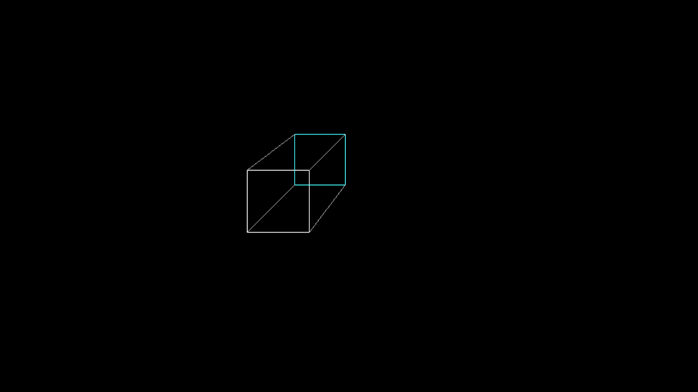
Output for Perspective Projection:
Output for Parallel Projection:

Question of Curiosity
Q.1] Differentiate between Parallel and Perspective Projections.
Ans.
Q2.] List various types of Projections and its sub types.
Ans. Projections are of 2 types Parallel projection and Perspective Projection.
Types of parallel projection:
1.Orthographic
2.Oblique
Three types of perspective projection:
1. 1-point perspective
2. 2-point perspective
3. 3-point perspective
Comments
Post a Comment