DLCOA - Verify the truth table of various logic gates using ICs and realize Boolean expressions using gates
EXPERIMENT NO.1
AIM: To study and verify the truth table of various logic gates using ICs and realize Boolean expressions using gates
Objectives:
- To implement basic gates (AND, OR, NOT) and verify their truth table.
- To implement universal gates (NAND, NOR) and verify their truth table
- To implement derived gates (XOR, XNOR) and verify their truth table.
CO’s to be achieved: 1 (Design and simulate different digital circuits)
PO’s to be achieved: PO1, PO2, PO3, PO10
APPARATUS REQUIRED:
THEORY:
Circuit that takes the logical decision and the process are called logic gates. Each gate has one or more input but only one output.
OR, AND, and NOT are basic gates. NAND, NOR and X-OR are known as Universal gates. Basic gates form these gates.
AND GATE:
The AND gate performs a logical multiplication commonly known as AND function. The output is high when both the inputs are high. The output is low level when any one of the inputs is low.
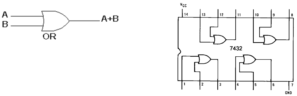
OR GATE:
The OR gate performs a logical addition commonly known as OR function. The output is high when any one of the inputs is high. The output is low level when both the inputs are low.
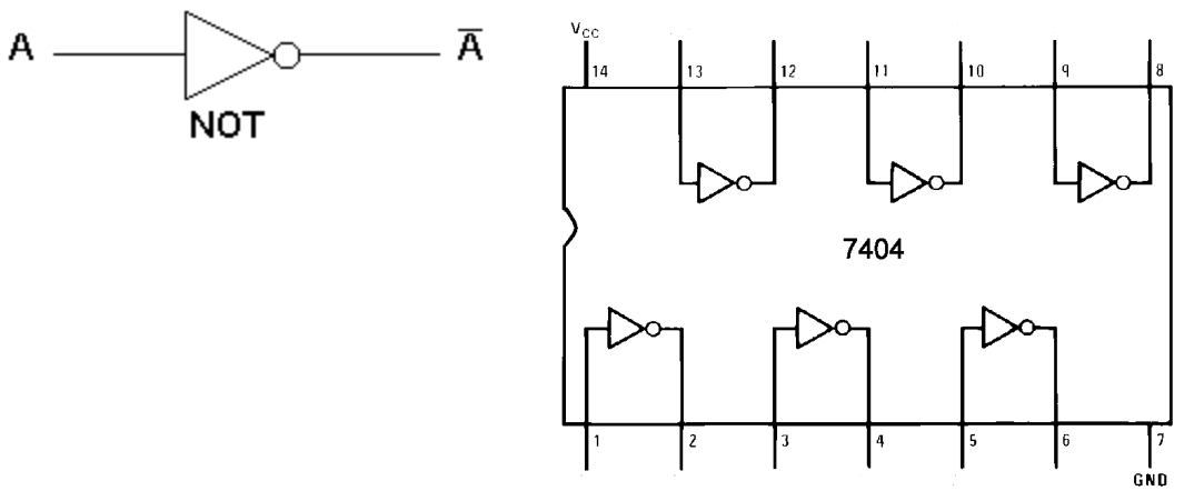
NOT GATE:
The NOT gate is called an inverter. The output is high when the input is low. The output is low when the input is high.
NAND GATE:
The NAND gate is a contraction of AND-NOT. The output is high when both the inputs are low and any one of the input is low. The output is low level when both the inputs are high.
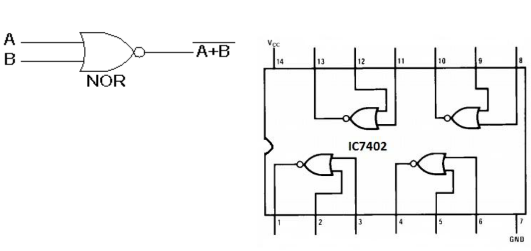
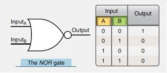
NOR GATE:
The NOR gate is a contraction of OR-NOT. The output is high when both inputs are low. The output is low one or both inputs are high.
X-OR GATE:
The output is high when any of the inputs is high. The output is low when both the inputs are low and both the inputs are high.
PROCEDURE:
Please refer virtual lab 1)https://de-iitr.vlabs.ac.in/ 2) http://vlabs.iitkgp.ernet.in/coa/
Connections are given as per circuit diagram.
Logical inputs are given as per circuit diagram.
Observe the output and verify the truth table.
AND GATE:

TRUTH TABLE:
OR GATE:
TRUTH TABLE:
NOT GATE:
TRUTH TABLE:
NAND GATE:

TRUTH TABLE:

NOR GATE:
TRUTH TABLE:
Output:


Conclusion:
We have studied and verified the truth table of various logic gates and realize Boolean expressions using gates.
Comments
Post a Comment